3 Speed Ceiling Fan Switch Wiring Diagram Wiring Diagram
Using wire connectors, connect the black wire from the ceiling fan to the black or red wire from the electrical box. Connect the white wire from the fan to the white wire from the box. Connect the green or bare copper wire from the fan to the green or bare copper wire from the box. Secure each connection with electrical tape. Step 5: Mount the Fan

3 Speed Ceiling Fan Wiring Diagram Wiring Harness Diagram
The wiring for a three-speed ceiling fan is relatively simple, and there are several wiring diagrams available online that provide step-by-step instructions for the process. Understanding how to correctly wire a three-speed ceiling fan can help ensure the best performance from the fan.
Hunter 3 Speed Fan Switch Wiring Diagram Wiring Diagram 3 Speed
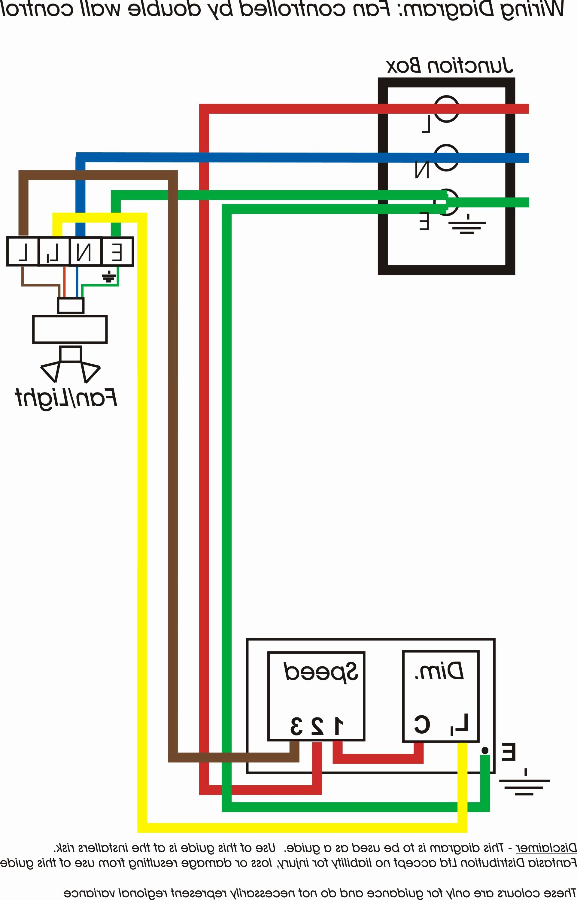
Connect the "L1" wire to the "H" terminal on the switch and the "L2" wire to the "N" terminal. Finally, connect the green wire to the "G" terminal on the switch. This will complete the wiring for the 3-speed ceiling fan switch. Now you know how to wire a 3-speed ceiling fan switch.

Table Fan Switch Wiring Diagram Easy Wiring
A wiring diagram for a 3 sd ceiling fan switch is a highly useful tool to have on hand when installing or repairing an electrical system. It allows the user to map out the various parts of the system in order to easily identify each individual component and how they interact with each other.
Ceiling Fan 3 Speed Wiring Diagram Database
The wiring diagram for a 3-speed ceiling fan includes terminals for the motor, switch, capacitor, and fan blades. It also includes information about the size and type of wire used in the installation, as well as the connections between the components. Properly connecting the wires is essential for the fan to work properly and safely.
3 speed ceiling fan with smart control homeautomation
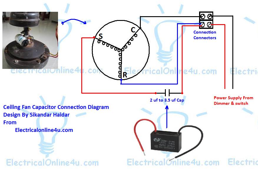
Ceiling fan capacitor connection diagram 3-wire ceiling fan capacitor diagram 5 wire ceiling fan capacitor diagram and installation Role of Capacitor in fan and single phase motor. So in the above diagram the speed switch contacts on L, 3, and 2.5 µF, and the fan on running or start on 2.5 microfarad Cap and on med speed.
Ceiling Fans Wiring Diagram
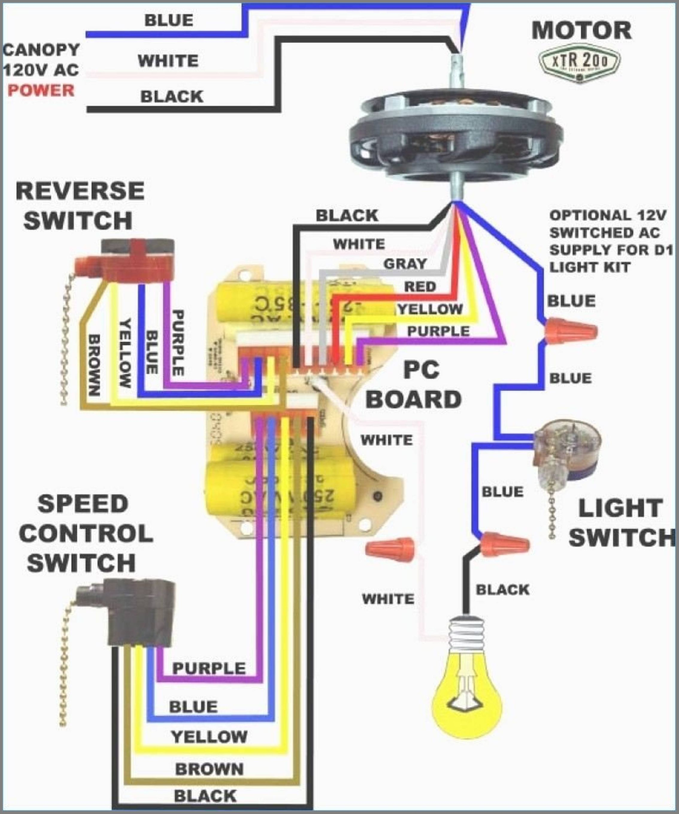
3 Speed Ceiling Fan Switch Wiring Diagram Community Helper Published on 2022-03-03 Download Download EdrawMax Edit Online A simplified wiring scheme shows how the switch connects to other components, like a capacitor, motor, pull-switch, and more.

Hampton Bay Ceiling Fan Wiring Schematic Free Wiring Diagram
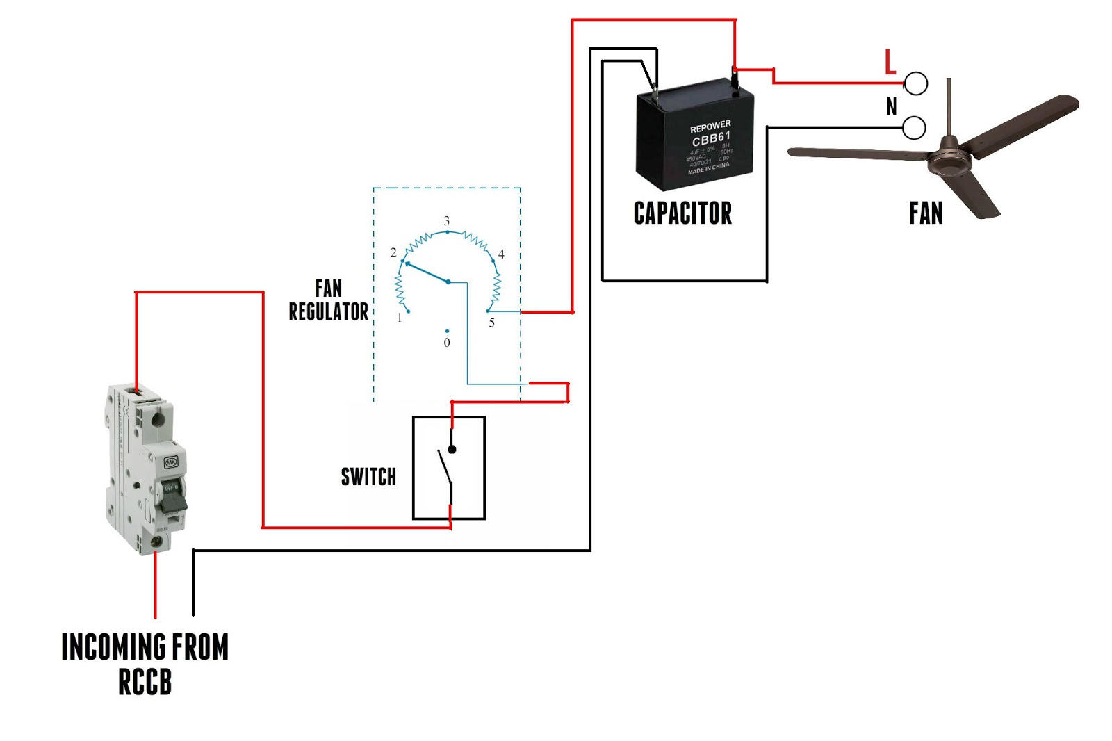
Wiring Diagram of 3 Speed Fan Capacitor Below is a basic and simple figure of an external connection that links the ceiling fan, fan speed regulator, and ON/OFF switch to a single-phase power supply at home. The internal connection of the running coil/winding, starting coil/winding, and the capacitor is also shown.

Ceiling Fan 3 Speed Wiring Diagram Database
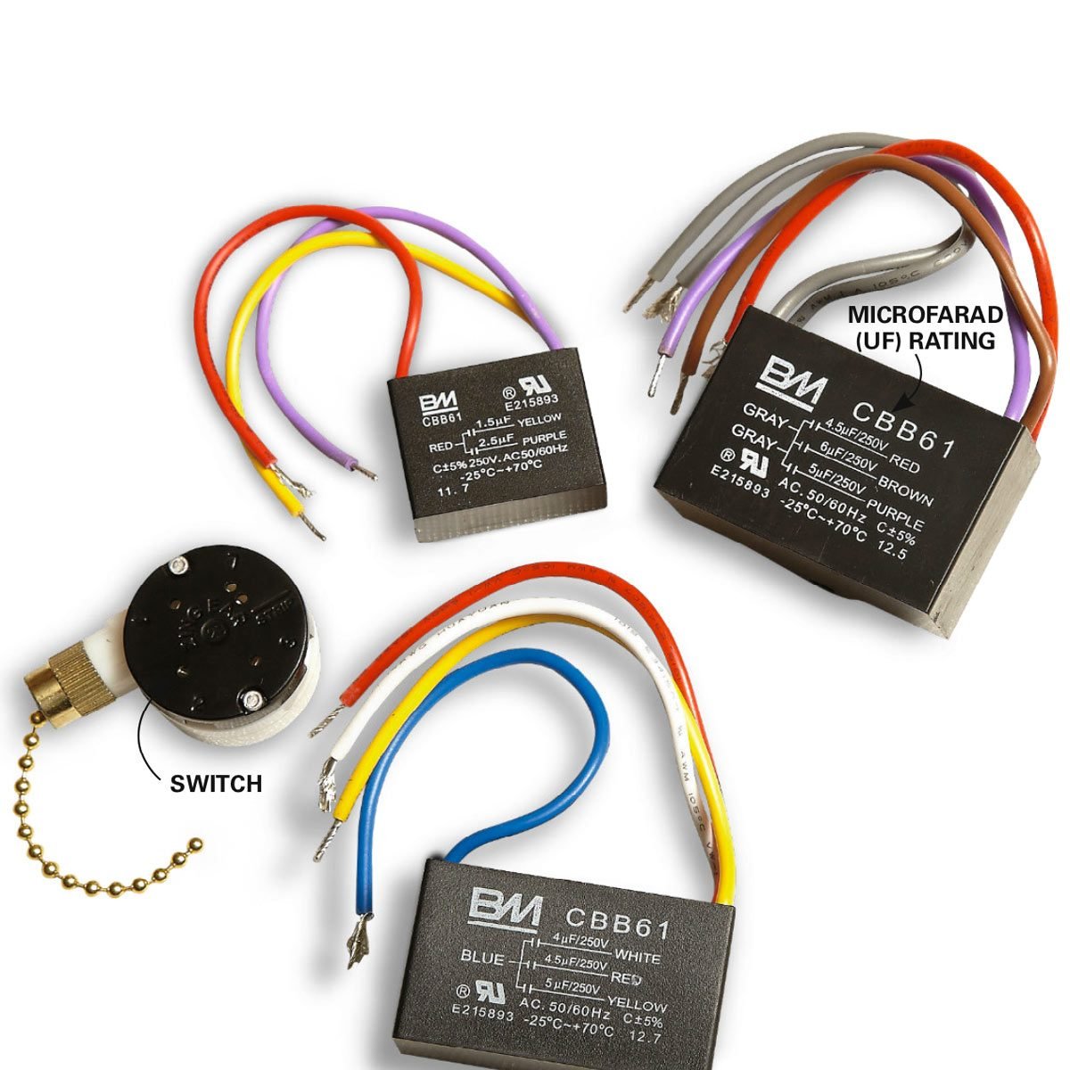
These signs include: The fan runs slowly at all speeds The fan fails to run completely at all speeds The fan won't run but spins when started with a hand Certain speeds do not work or are slower than expected The motor turns freely by hand but will not spin. The capacitors are housed in a black box inside the switch housing of the fan.
hampton bay ceiling fan switch wiring diagram
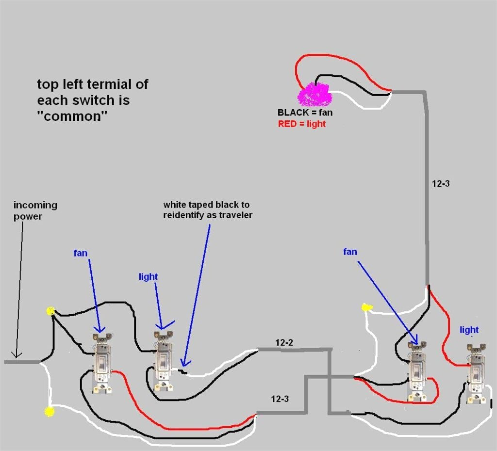
1. First, shut off the power supply to the fan switch. This is an important safety measure to ensure that no one gets electrocuted during the wiring process. 2. Now, take the power source and connect it to the fan switch. This can be done by connecting the black wire to one of the contacts on the fan switch.

bookingritzcarlton.info Kipas angin gantung, Diagram
The power wire should be attached to the "L" terminal, the neutral wire to the "N" terminal, and the ground wire to the "G" terminal. After that, you can attach the start and run capacitors to their respective terminals. Finally, you can plug the fan into an outlet and test it to make sure it's working properly.
3 Speed Ceiling Fan Wiring Diagram Wiring Harness Diagram
Understanding 3 speed ceiling fan wiring diagrams can be complicated but is an essential part of home maintenance. With some patience and a little practice, anyone can become a pro at interpreting wiring diagrams and troubleshooting ceiling fans. By taking the time to learn and understand wiring diagrams, you will be able to keep your ceiling.
Ceiling fan Capacitor Wiring Connection Diagram Electrical Online 4u
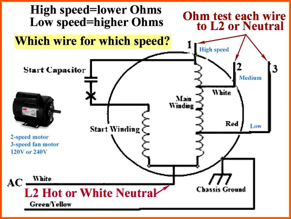
L: line from motor housing 1: yellow from capacitor (6µF, 200V) 2: black from capacitor 3: red from capacitor (3.5µF, 200V) Since this will connect the line & 6µF on high speed setting, and line, black and 3.5µF on medium speed setting, the black and yellow wires appear to be swapped. Should the correct wiring be as following? Switch:

Pin on Электрика
1. Connect the Black power supply wire to the "L" terminal on the switch to power the fan motor. 2. Connect the Purple wire to the "1" terminal - the fan's low speed. 3. Connect the Brown wire to the "2" terminal - the fan's middle speed. 4. Connect the Gray wire to the "3" terminal - the fan's highest speed.
[3+] Hampton Bay Ceiling Fan Diagram, Get Hunter Ceiling Fan Wiring
A 3 sd ceiling fan wiring diagram is a visual representation of the fan's electrical components. It shows the various connections between the fan's motor and switches, as well as the connections to the power source.

ME LENTA [26+] Hampton Bay Ceiling Fan Diagram, Hampton Bay 3 Speed
The wiring diagram of a 3-speed ceiling fan is essential for any homeowner or electrician looking to install or repair a fan. With this diagram, they can easily identify what type of wire and connections are needed for the fan to work properly. The wiring diagram also helps determine the best location in the house to mount the fan and how much.